
Danger: Before you begin to install this product, read the safety information in Caution: Safety Information--Read This First, SD21-0030. This booklet describes safe procedures for cabling and plugging in electrical equipment.
GA27-4226
D310/656
| Note |
|---|
|
Before using this information and the product it supports, be sure to read the safety information under "Safety Information" and the general and emissions notices in Appendix B. "Notices". |
Second Edition (August 1999)
This edition applies to the IBM 8371-A16 Networking Multiprotocol Ethernet Switch.
Order publications through your IBM representative or the IBM branch office serving your locality. Publications are not stocked at the address given below.
A form for readers' comments appears at the back of this publication. If the form has been removed, address your comments to:
Department CGF
© Copyright International Business Machines Corporation 1999. All rights reserved.
Note to U.S. government Users -- Documentation related to restricted rights -- Use, duplication or disclosure is subject to restrictions set forth in GSA ADP Schedule contract with IBM Corp.
Chapter 4. Problem Determination
Appendix A. Physical Characteristics and Requirements
1-1. 8371-A16 Networking Multiprotocol Ethernet Switch
1-2. Front Panel
1-3. Rear Panel
1-4. Null Modem Cable Pin Assignments
2-1. Ethernet network using 8371
3-1. Rack-Mounting the 8371
3-2. Installing a Blade
3-3. The Feature Modules
3-4. Installing a Feature Module
4-1. Front Panel of the 8371
4-2. Problem Solving for the 8371
4-3. Front Panel of the FX Feature Module
4-4. Front Panel of the TX Feature Module
4-5. Front Panel of the ATM Feature Module
1-1. Recommended Maximum Cable Lengths
3-1. Ethernet Desktop Installation Procedures
4-1. 8371 LEDs
4-2. 8-port 10/100 TX Feature Module LEDs
4-3. 100BASE-FX and ATM155 Blade LEDs
A-1. Operating Environment - 8371-A16 Networking Multiprotocol Ethernet Switch

Danger: Before you begin to install this
product, read the safety information in Caution:
Safety Information--Read This First, SD21-0030.
This booklet describes safe procedures for cabling and plugging in
electrical equipment.

Gevaar: Voordat u begint met de
installatie van dit produkt, moet u eerst de
veiligheidsinstructies lezen in de brochure
PAS OP! Veiligheidsinstructies--Lees
dit eerst, SD21-0030.
Hierin wordt beschreven hoe u electrische apparatuur
op een veilige manier moet bekabelen en aansluiten.

Perigo: Antes de começar a instalar
este produto, leia as informações de segurança
contidas em Cuidado: Informações Sobre
Segurança--Leia Isto Primeiro, SD21-0030.
Esse folheto descreve procedimentos de segurança para
a instalação de cabos e conexões em equipamentos
elétricos.



Fare! Før du installerer
dette produkt, skal du læse sikkerhedsforskrifterne
i NB: Sikkerhedsforskrifter--Læs
dette først SD21-0030.
Vejledningen beskriver den fremgangsmåde, du skal bruge
ved tilslutning af kabler og udstyr.

Gevaar Voordat u begint met
het installeren van dit produkt, dient u eerst
de veiligheidsrichtlijnen te lezen die zijn vermeld in de publikatie
Caution: Safety Information - Read This
First, SD21-0030. In dit boekje vindt u veilige procedures voor
het aansluiten van elektrische appratuur.

VAARA: Ennen kuin aloitat
tämän tuotteen asennuksen, lue
julkaisussa Varoitus: Turvaohjeet--Lue
tämä ensin, SD21-0030, olevat turvaohjeet.
Tässä kirjasessa on ohjeet
siitä, miten sähkölaitteet kaapeloidaan ja
kytketään turvallisesti.

Danger : Avant d'installer
le présent produit, consultez le livret
Attention : Informations pour la
sécurité -- Lisez-moi d'abord,
SD21-0030, qui décrit les procédures
à respecter pour effectuer les opérations
de câblage et brancher les équipements
électriques en toute sécurité.

Vorsicht: Bevor mit der Installation
des Produktes begonnen wird, die Sicherheitshinweise
in Achtung: Sicherheitsinformationen--Bitte
zuerst lesen, IBM Form SD21-0030.
Diese Veröffentlichung beschreibt die Sicherheitsvorkehrungen
für das Verkabeln und Anschließen elektrischer Geräte.


Vigyázat:
Mielôtt megkezdi a berendezés üzembe helyezését,
olvassa el a Caution: Safety Information--
Read This First, SD21-0030 könyvecskében leírt
biztonsági információkat.
Ez a könyv leírja, milyen biztonsági intézkedéseket
kell megtenni az elektromos berendezés huzalozásakor illetve
csatlakoztatásakor.

Pericolo: prima di iniziare l'installazione
di questo prodotto, leggere le informazioni relative alla
sicurezza riportate nell'opuscolo
Attenzione:
Informazioni di sicurezza -- Prime informazioni da leggere
in cui sono descritte le procedure per il cablaggio ed
il collegamento di apparecchiature elettriche.


Fare: Før du begynner å installere
dette produktet, må du lese sikkerhetsinformasjonen
i Advarsel: Sikkerhetsinformasjon -- Les
dette først, SD21-0030 som beskriver
sikkerhetsrutinene for kabling og tilkobling av elektrisk utstyr.


Perigo: Antes de iniciar a instalação deste
produto, leia as informações de segurança
Cuidado: Informações de
Segurança -- Leia Primeiro, SD21-0030.
Este documento descreve como efectuar, de um modo seguro,
as ligações eléctricas dos equipamentos.


Peligro: Antes de empezar
a instalar este producto, lea la información de seguridad
en Atención: Información de Seguridad --
Lea Esto Primero, SD21-0030.
Este documento describe los procedimientos de seguridad
para cablear y enchufar equipos eléctricos.

Varning -- livsfara: Innan du
börjar installera den här produkten bör du läsa
säkerhetsinformationen i dokumentet Varning:
Säkerhetsföreskrifter-- Läs detta först,
SD21-0030.
Där beskrivs hur du på ett säkert sätt ansluter
elektrisk utrustning.


Caution:
Double-pole/neutral fusing in the power supply. Power may be present in the product unless the power cord is unplugged.

Waarschuwing:
Dubbelpool/neutraal zekering in de voedingseenheid. Er kan spanning in het product aanwezig zijn zolang de stekker in het stopcontact zit.

Cuidado:
Fusıvel bipolar/neutro na fonte de alimentaşo. Pode haver energia presente no produto, a menos que o cabo de alimentaşo esteja desconectado.

Pas på!
Strømforsyningsenheden er sikret til brug ved 110 og 220 volt. Der kan være spænding i produktet, medmindre netledningen er trukket ud.

Waarschuwing:
Dubbelpool/neutraal zekering in de voedingseenheid. Er kan spanning in het product aanwezig zijn zolang de stekker in het stopcontact zit.

VAARA:
Virtalähde on varustettu kaksinapaisella sulakkeella, jossa on myös maanapa. Tuotteessa voi olla jännite, jos verkkojohtoa ei ole irrotettu.

ATTENTION :
L'un des deux fusibles est sur le neutre. L'alimentation électrique est protégée par fusibles sur les deux pôles (phase et neutre). Présence de courant possible sauf si le cordon d'alimentation est débranché.

Achtung:
Zweipolige bzw. Neutralleiter-Sicherung im Netzteil. Netzstecker ziehen, um sicherzustellen, daß keine Spannung am Gerät anliegt.

Attenzione:
L'alimentatore contiene fusibili su fasi/neutro. Può essere presente tensione nell'apparecchiatura se il cavo di alimentazione è collegato.

Advarsel:
Topolet/nøytral sikring i strømforsyningsenheten. Det kan være strøm i maskinen hvis ikke nettkabelen er dratt ut.

CUIDADO:
Protecção (por fusíveis) bipolar com neutro na fonte de alimentação. A menos que o cabo de alimentação esteja desligado, o produto pode estar sob tensão.

Precaución:
Hay una fusión de doble polo/neutro en la fuente de alimentación. El producto podría estar cargado eléctricamente a menos que el cable de alimentación esté desconectado.

VARNING: Nätaggregatet är dubbelpoligt avsäkrat. Det kan finnas ström i produkten såvida inte nätkabeln är urkopplad.


This manual explains how to plan for and install the 8371-A16 Networking Multiprotocol Ethernet Switch, the 8265-L3S and the 8260-L3S.
This manual is intended for use by installation technicians and network administrators.
This chapter describes the features of the 8371-A16 Networking Multiprotocol Ethernet Switch, the 8265-L3S (8371 blade version for the 8265), and the 8260-L3S (8371 blade version for the 8260), and provides a functional overview that can help you integrate the products into your new or existing network. Both products have the same function, and will be referred to as 8371 in this publication.
The 8371 is an intelligent managed switch, designed for use in medium-sized workgroups or remote locations that are part of a large network.
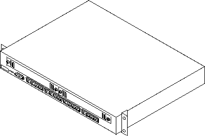
The 8371-A16 Networking Multiprotocol Ethernet Switch, the 8265-L3S, and the 8260-L3S have all the connectors and light-emitting diodes (LEDs) on the front, with the exception of the power cord and the 10/100BASE-TX Ethernet service port, which are on the back.
The 8371 also has one standard serial service port: an EIA/TIA 232 male 9-pin D-shell connector. (In the 8265-L3S and the 8260-L3S, the EIA/TIA 232 service port is identified as an RS-232 port.) The serial service port can be attached locally through a null modem cable or remotely through a modem attachment.
See Appendix A. "Physical Characteristics and Requirements" for a description of physical and environmental characteristics of the 8371. Figure 1-4 shows the pin assignments for the EIA/TIA 232 service port.
Figure 1-1. 8371-A16 Networking Multiprotocol Ethernet Switch
 |
The 8371 contains the following features:
Figure 1-2 shows the indicators and ports on the front panel of the 8371.
 |
Figure 1-3 shows the rear panel of the 8371.
 |
The following types of ports are available on the 8371.
The last 8 digits of the base MAC Address of the 8371 are printed on a label on the front of the 8371. The first 4 digits of the base MAC Address are not on the label. You can get the numbers through a console session.
The management port is an EIA/TIA 232 port that is used to configure the 8371 using an ASCII terminal.
Cable and connector requirements differ depending on the port to which each cable connects.
Table 1-1. Recommended Maximum Cable Lengths
| Ethernet Type | Maximum Segment Length |
|---|---|
| 10/100BASE-TX | 100 m (328 ft) |
| 100BASE-FX | 412 m (1352 ft) for half-duplex
2000 m (6562 ft) for full-duplex |
The 8371 uses 16 RJ-45 connectors. For connection to 10/100BASE-TX networks, you should use UTP/STP category 3, 4, or 5 cables. For connection to 100BASE-TX networks, you can use only category 5 cables. STP requires a user-provided 100-ohm/150-ohm balun.
This blade uses 16 MT-RJ-type connectors. Use multimode optical fiber that meets the specifications in EIA/TIA 568A or ISO/IEC 11801. The maximum length of optical fiber cable between devices should not exceed 2000 m (6562 ft) if the link is used in full-duplex mode. If the link is used in half-duplex mode, the length should not exceed 412 m (1352 ft).
This expansion module uses 8 RJ-45 connectors. For connection to 10/100BASE-TX networks, you should use UTP/STP category 3, 4, or 5 cables. For connection to 100BASE-TX networks, you can use only category 5 cables. STP requires a user-provided 100-ohm/150-ohm balun.
This blade uses 8 MT-RJ-type connectors. Use multimode optical fiber that meets the specifications in EIA/TIA 568A or ISO/IEC 11801. The maximum length of optical fiber cable between devices should not exceed 2000 m (6562 ft) if the link is used in full-duplex mode. If the link is used in half-duplex mode, the length should not exceed 412 m (1352 ft).
This module uses 2 SC-type connectors. For connection to 155Mbps ATM networks, use 62.5-micron, plenum-rated, multimode optical fiber.
The management port is a standard DB-9 male connector that provides an EIA/TIA 232 serial interface. You can connect using a null-modem cable to a local workstation or a standard serial cable to a modem for a remote connection. Once connected you can manage the 8371. This is called out-of-band management.
Note: You can make a null-modem cable by connecting a null-modem adapter to a standard serial cable.
Figure 1-4. Null Modem Cable Pin Assignments
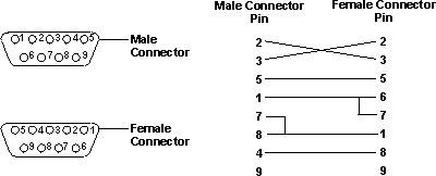 |
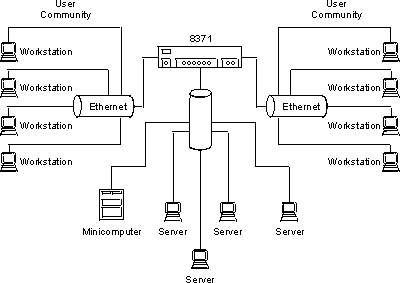
Figure 2-1 shows a typical Ethernet network arrangement, including an 8371-A16 Networking Multiprotocol Ethernet Switch.
Figure 2-1. Ethernet network using 8371
 |
Before installing the 8371, be sure to read "Safety Information" and the notices and warranty information in Appendix B. "Notices".
This chapter provides step-by-step instructions for installing the 8371.
Table 3-1. Ethernet Desktop Installation Procedures
| Step | Procedure | Reference |
|---|---|---|
| 1. | Read the safety booklet. | SD21-0030 |
| 2. | Unpack the 8371 | "Unpacking Instructions" |
| 3. | Rack-mount the 8371 | "Rack-Mounting the 8371" |
| 4. | Install an Optional Module | "Installing a Feature Module" |
| 5. | Perform power-on checkout | "Power-On Checkout" |
| 6. | Connect the Cables | "Cabling" |
| 7. | Plan and configure the 8371 | Chapter 2. "Network Planning" |
If you choose rack-mounting, you must provide the rack; it is not provided with the 8371.
You can use any EIA standard 19-inch rack. The rack can be open or closed. However, if you choose a closed rack, you must make sure that enough air flows through the 8371. Covers on the front of the rack that would not let air reach the 8371 must be removed or modified to let air pass. Similarly, unvented rear rack covers that would not let air exit the 8371 or would cause back pressure to build up from several machines must not be used.
The 8371 can be installed on a flat level surface or it can be installed in a standard 19-inch rack. To install the 8371 in a rack, refer to Figure 3-1 and perform the following steps.
Note: The rack-mounting screws are not provided. Ensure that the ventilation holes are not obstructed.
Figure 3-1. Rack-Mounting the 8371
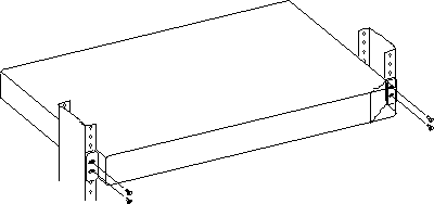 |
Figure 3-2. Installing a Blade
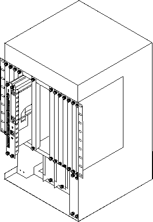 |
Installing the blade does not require you to power down the 8265 or 8260; you can hot-swap the blade.
Grasp the blade by the top and bottom of the faceplate. Carefully insert the blade into its slot and guide it straight while pressing evenly and firmly to correctly seat the connectors into the hub backplane.
When it is completely seated, close the latches and tighten the thumb-screws to secure the blade.
Important: 8371 feature modules are hot-swappable and can be inserted and removed from the 8371 without disconnecting the power.
Prior to hot-swapping an 8371 feature module, you must disable the feature module ports. Use the + disable slot n (where n is the slot number) command from t 5 to disable all ports on the slot. After replacing the feature module, use the + enable slot n command from t 5 to test all of the ports.
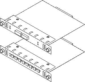
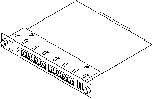
Three feature modules are available for the 8371: 2-Port ATM155, 8-Port 100BASE-FX, and 8-Port 10/100BASE-TX.
Figure 3-3. The Feature Modules
  |
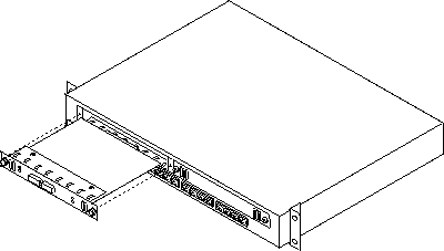
To install these modules, perform the following steps:
Figure 3-4. Installing a Feature Module
 |
Additionally, the System Card Status green LED should be on and the System Card Status Yellow LED should be Off. If the LEDs are not in the correct state, call your service representative.
For information about attaching cables to the newly installed feature module, see "Cabling".
Prior to hot-swapping an 8371 feature module, you must disable the feature module ports. Use the + disable slot n (where n is the slot number) command from t 5 to disable all ports on the slot. After replacing the feature module, use the + enable slot n command from t 5 to test all of the ports.
Connect the AC power cable from the back panel to the power source. This powers on the 8371.
At power on, the power, fault, and OK LEDs should be lit. The fault LED will turn off within several seconds. The OK LED should start to blink, then turn on solid once the 8371 is operational. For more information about the LEDs, see "8371 LED Indicators".
Cable Tips
You can connect the management port directly to a local workstation by using a null-modem cable, or you can use a serial cable and a modem to connect to a remote workstation.
To access the 8371 locally, perform the following steps.
To access the 8371 remotely, perform the following steps.
For information on setting up a session through the management port, see 8371 Networking Multilayer Ethernet Switch Software User's Guide and Configuration Reference.
See 8371 Networking Multilayer Ethernet Switch Software User's Guide and Configuration Reference.
This chapter briefly describes methods of diagnosing hardware problems.
Both hardware and software (operational code and configuration) problems can affect the 8371. LEDs, diagnostic programs, and error messages provide information needed for problem determination. This manual is chiefly concerned with diagnosing and correcting hardware problems, but it includes some software information for your convenience.
Generally, errors that occur before the operational code is loaded are hardware-related. LEDs on the front of the 8371 are indicators of the status of hardware components within the 8371.
Go to "8371 LED Indicators" for LED status and indicators for the 8371.
See "Installing a Feature Module" for information on removal and replacement procedures for optional modules.
Generally, errors that occur after the operational code is loaded indicate problems with the operational code or configuration file.
Error codes and corrective action are described in the 8371 Networking Multilayer Ethernet Switch Software User's Guide and Configuration Reference.
Figure 4-1 shows the locations of the LEDs, and Table 4-1 indicates the meaning of the LEDs.
Figure 4-1. Front Panel of the 8371
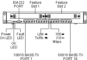 |
| LED | Color | State | Explanation |
|---|---|---|---|
| I (Power On) | Green | ON |
|
| OFF |
| ||
| OK | Green | ON | Operational code has loaded without a fault. |
| OFF | Operational code has not loaded or has failed. | ||
| Flickering | Operational code load is in process. | ||
| Fault | Yellow | ON | Indicates a hardware fault. |
| OFF | No hardware fault. | ||
| Right Ethernet Port LED | Green | ON | 100 Mbps |
| OFF | 10 Mbps | ||
| Left Ethernet Port LED | Green | ON | Link |
| Flickering | TxRx traffic |
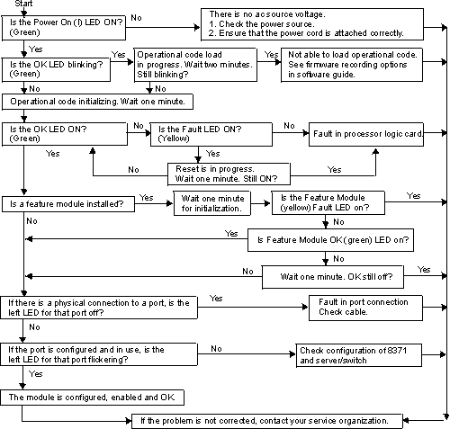
Use the following chart to determine the correct course of action concerning your 8371.
Figure 4-2. Problem Solving for the 8371
 |
This section describes the LED status indicators for the 8371 feature modules.
Generally, errors occurring before the operational code is loaded are hardware-related. LEDs on the front of the 8371 reflect the status of the hardware components within the 8371.
Figure 4-3, Figure 4-4, and Figure 4-5 show the location of the LEDs, and Table 4-2 indicates the meaning of the LEDs.
Figure 4-3. Front Panel of the FX Feature Module
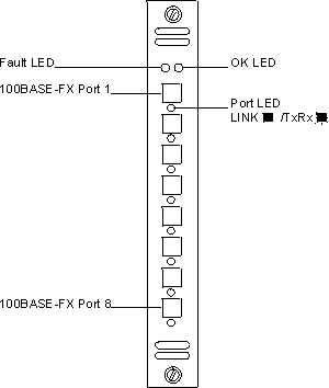 |
Figure 4-4. Front Panel of the TX Feature Module
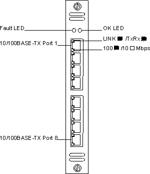 |
Figure 4-5. Front Panel of the ATM Feature Module
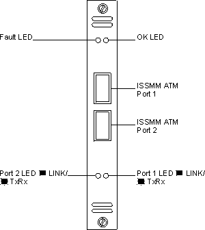 |
Table 4-2. 8-port 10/100 TX Feature Module LEDs
| LED | Color | State | Explanation |
|---|---|---|---|
| OK | Green | ON | Module is operational. |
| OFF | Module is not operational. | ||
| Fault | Yellow | ON | Indicates a hardware fault. |
| OFF | No hardware fault. | ||
| Bottom Ethernet Port LED | Green | ON | 100 Mbps |
| OFF | 10 Mbps | ||
| Top Ethernet Port LED | Green | ON | Link |
| Flickering | TxRx traffic |
Table 4-3. 100BASE-FX and ATM155 Blade LEDs
| LED | Color | State | Explanation |
|---|---|---|---|
| OK | Green | ON | Module is operational. |
| OFF | Module is not operational. | ||
| Fault | Yellow | ON | Indicates a hardware fault. |
| OFF | No hardware fault. | ||
| Port LED | Green | ON | Link |
| Flickering | TxRx traffic |
Width: 439 mm (17.3 in.)
Depth: 355.6 mm (14 in.)
Height: 64 mm (2.5 in.)
Front: Adequate space to view LEDs
Sides: 50.8 mm (2 in.)
Rear: 50.8 mm (2 in.)
Maximum input power is 150W.
Table A-1. Operating Environment - 8371-A16 Networking Multiprotocol Ethernet Switch
| Operating Temperature | 10°C to 40° C (50° to 104° F) |
| Storage Temperature | 1° C to 60° C (33.8° to 140° F) |
| Operating Humidity | 8% to 80% non-condensing |
IBM may not offer the products, services, or features discussed in this document in other countries. Consult your local IBM representative for information on the products and services currently available in your area. Any reference to an IBM product, program, or service is not intended to state or imply that only that IBM product, program, or service may be used. Any functionally equivalent product, program, or service that does not infringe any IBM intellectual property right may be used instead. However, it is the user's responsibility to evaluate and verify the operation of any non-IBM product, program, or service.
IBM may have patents or pending patent publications covering subject matter described in this document. The furnishing of this document does not give you any license to these patents. You can send license inquiries, in writing, to:
IBM Director of Licensing
IBM Corporation
North Castle Drive
Armonk, NY 10504-1785
U.S.A.
The following paragraph does not apply to the United Kingdom or any country where such provisions are inconsistent with local law: INTERNATIONAL BUSINESS MACHINES CORPORATION PROVIDES THIS PUBLICATION "AS IS" WITHOUT WARRANTY OF ANY KIND, EITHER EXPRESS OR IMPLIED, INCLUDING, BUT NOT LIMITED TO, THE IMPLIED WARRANTIES OF MERCHANTABILITY OR FITNESS FOR A PARTICULAR PURPOSE. Some states do not allow disclaimer of express or implied warranties in certain transactions, therefore, this statement may not apply to you.
This publication could include technical inaccuracies or typographical errors. Changes are periodically made to the information herein; these changes will be incorporated in new editions of the publication. IBM may make improvements and/or changes in the product(s) and/or program(s) described in this publication at any time.
This Class A digital apparatus complies with Canadian ICES-003.
Cet appareil numérique de la classe A est conformé à la norme NMB-003 du Canada.
This product is in conformity with the protection requirements of EC Council Directive 89/336/EEC on the approximation of the laws of the Member States relating to electromagnetic compatibility.
IBM cannot accept responsibility for any failure to satisfy the protection requirements resulting from a non-recommended modification of the product, including the fitting of non-IBM option cards.
This product has been tested and found to comply with the limits for Class A Information Technology Equipment according to CISPR 22/European Standard EN 55022. The limits for Class A equipment were derived for commercial and industrial environments to provide reasonable protection against interference with licensed communication equipment.
Warning!
This is a Class A product.
In a domestic environment this product may cause radio interference
in which case the user may be required to take adequate measures.
Zulassungsbescheinigung laut dem Deutschen Gesetz über die elektromagnetische Verträglichkeit von Geräten (EMVG) vom 30. August 1995 (bzw. der EMC EG Richlinie 89/336).
Dieses Gerät ist berechtigt in Übereinstimmung mit dem Deutschen EMVG das EG-Konformitätszeichen - CE - zu führen.
Verantwortlich für die Konformitätserklärung
nach Paragraph 5 des EMVG ist die
IBM Deutschland Informationssysteme GmbH, 70548 Stuttgart.
Informationen in Hinsicht EMVG Paragraph 3 Abs. (2) 2:
| Das Gerät erfüllt die Schutzanforderungen nach EN 50082-1 und EN 55022 Klasse A. |
EN 55022 Klasse A Geräte müssen
mit folgendem Warnhinweis versehen werden:
"Warnung: dies ist eine Einrichtung der Klasse A.
Diese Einrichtung kann
im Wohnbereich Funkstörungen verursachen;
in diesem Fall kann vom
Betreiber verlangt werden,
angemessene Maßnahmen durchzuführen und dafür
aufzukommen."
EN 50082-1 Hinweis:
"Wird dieses Gerät in einer industriellen
Umgebung betrieben (wie in
EN 50082-2 festgelegt), dann kann es dabei eventuell gestört werden.
In solch einem Fall ist der Abstand bzw. die Abschirmung zu der
industriellen Störquelle zu vergrößern."
Anmerkung:
Um die Einhaltung des EMVG sicherzustellen sind die Geräte,
wie in den
IBM Handbüchern angegeben, zu installieren und zu betreiben.
This product is a Class A Information Technology Equipment and conforms to the standards set by the Voluntary Control Council for Interference by Technology Equipment (VCCI). In a domestic environment this product may cause radio interference in which case the user may be required to take adequate measures.

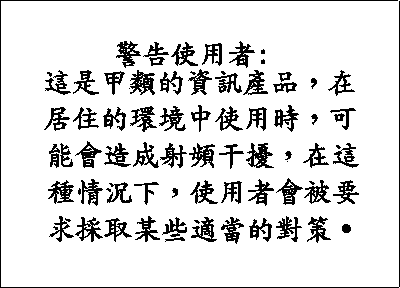
Please note that this device has been certified for business purpose with regard to electromagnetic interference. If you find this is not suitable for your use, you may exchange it for one of residential use.
Class 1 LED Product
LED Klasse 1
LED Klass 1
Luokan 1 Ledlaite
Appareil À LED de Classe 1
To IEC 825-1:1993
Class 1 Laser Product
Laser Klasse 1
Laser Klass 1
Luokan 1 Laserlaite
Appareil À Laser de Classe 1
To IEC 825-1:1993
The following terms are trademarks of the
IBM Corporation in the United States or other countries or both:
| AIX | IBM |
| Nways |
|
Microsoft, Windows, Windows NT, and the Windows 95 logo are trademarks or registered trademarks of Microsoft Corporation.
Other company, product and service names may be trademarks or service marks of other companies.